5. Visualization
5.1. Snapshot Image Viewer
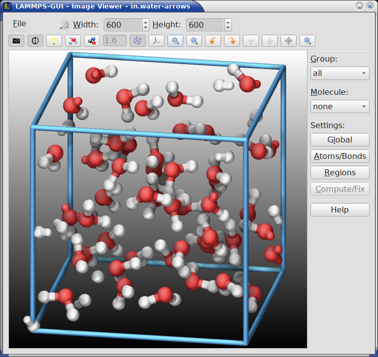
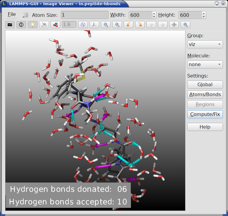
By selecting the Create Image entry in the Run menu, or by hitting the Ctrl-I (Command-I on macOS) keyboard shortcut, or by clicking on the “palette” button in the status bar of the Editor window, LAMMPS-GUI sends a custom write_dump image command to LAMMPS and reads back the resulting snapshot image with the current state of the system into an image viewer. This functionality is not available during an ongoing run. In case LAMMPS is not yet initialized, LAMMPS-GUI tries to identify the line with the first run or minimize command and execute all commands in the editor up to that line, and then executes a “run 0” command. This initializes the system so an image of the initial state of the system that can be rendered. If there was an error in that process, a dialog with the error message will appear.
5.1.1. Automatic settings
When possible, LAMMPS-GUI tries to detect which elements the atoms correspond to (via their mass) and then colorizes them in the image and sets their atom diameters accordingly. If this is not possible - for instance when using reduced (= ‘lj’) units - then LAMMPS-GUI will check the current pair style and if it is a Lennard-Jones type potential, it will extract the sigma parameter for each atom type and assign atom diameters from those numbers. When using an atom style where the atom diameters are set directly on a per-atom basis, LAMMPS will use that value. For cases where atom diameters are not auto-detected or you want to override the choice, you can configure it in the Atom/Bond settings dialog (see below). The default value is inferred from the x-direction lattice spacing.
For particles that use atom styles “body”, “ellipsoid”, “line”, or “tri” LAMMPS will visualize the particles according to their atom style information by default. Other particles types will be visualized as sphere. In the Atom/Bond settings dialog, this can be further customized (or disabled).
It is also possible to visualize regions, graphics from computes and fixes, and have bonds computed dynamically for potentials, where the bonds are determined implicitly (like AIREBO). Please see the documentation of the dump image command for more details on these and other features and the LAMMPS Visualization Howto for more general discussions on how to generate advanced visualizations with LAMMPS directly.
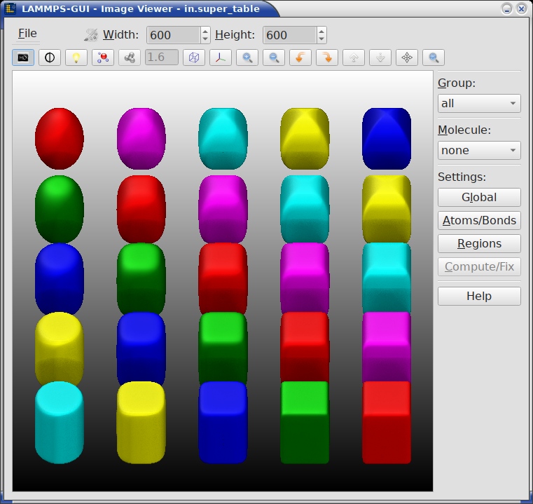
If elements cannot be detected, the default sequence of colors of the dump image command is assigned to the different atom types.
5.1.2. Customizations
The Image Viewer controls described below support significant customization of the default visualization through the toolbar buttons, editable text fields, and additional dialogs. This covers a wide variety of possible customizations. After each change is applied, LAMMPS-GUI will have LAMMPS re-create the displayed image with the updated settings. The resulting image can be saved or copied to the clipboard and pasted into a compatible application.
Delays in updating the image
Some visualization settings, especially enabling SSAO and FSAA (see
below) or massively enlarging the image size, can significantly
increase the time required for LAMMPS to render the image. While in
most cases the image will be updated in a fraction of a second,
complex visualizations may take multiple seconds. While LAMMPS is
rendering an updated image, the small color palette icon in the
menu bar is colored  and will be grayed out
  when
rendering is complete.
when
rendering is complete.
For further customization or making the visualization available when running the simulation with LAMMPS directly (e.g. when running on a cluster after enlarging the system), you can copy the current dump image and dump_modify commands to the clipboard so they can be pasted into a LAMMPS input file in either the included text editor window or some other text editor and adjusted according to the documentation.
The resulting images will be shown automatically in the slide show viewer when running the simulation with the thus modified input from LAMMPS-GUI. This strategy has been used to great effect to create many of the simulation snapshot images shown in this documentation and the LAMMPS manual.
5.1.3. Color customizations
LAMMPS-GUI uses two lists of colors. The first are the per-type atom colors that can be customized from a built-in initial assignment. This list is maintained by LAMMPS-GUI and information from them is passed to LAMMPS via LAMMPS commands while creating colors named “type#” where ‘#’ is the atom type number. These color definitions can also be written to and loaded from JSON files. Recent LAMMPS versions have a dump_modify loadcolors and savecolors command that can read and write files in the same format. The second is the list of named colors that are maintained by the dump image command in LAMMPS. LAMMPS-GUI has the list of predefined color names and may define additional colors as needed, but will give them names that are specific to LAMMPS-GUI and does not attempt to overwrite any of the predefined colors.
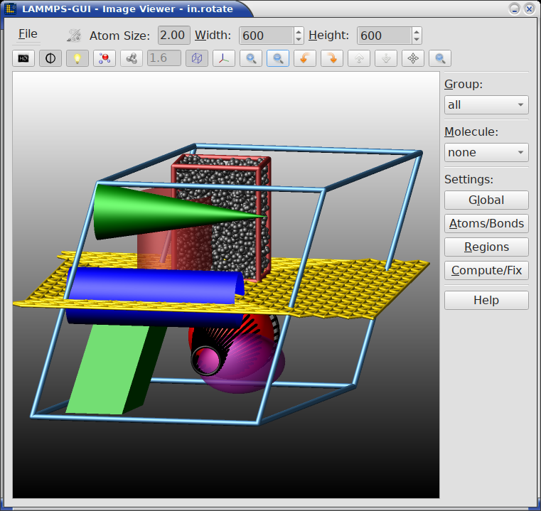
5.1.4. Available controls
The Image Viewer window consists of three main areas: a menu/toolbar strip at the top, the rendered image in the center, and a settings panel on the right side. Following the general theme of LAMMPS-GUI of extensive keyboard shortcut support, you can select most text fields by using the Alt key and the underlined letter. For example the File menu is opened with Alt-F and its entries can be also selected the same way or using the cursor keys and Enter. Keyboard shortcuts starting with Ctrl usually work globally inside the image window, that is even when the corresponding menu item is not visible.
The menu/toolbar strip consists of two rows: the first row with the File menu, atom and bond size controls, image dimension controls, and a second row of toggle and action buttons.
The menu bar row has:
- The File menu with the following entries:
Save As… (Ctrl-S): Save the rendered image to a file. The file format is inferred from the file name extension. When the ImageMagick software is installed, additional file formats beyond those natively supported by the Qt library become available.
Copy Image (Ctrl-C): Copy the rendered image to the clipboard for pasting it into another application. This requires support from the receiving application, which is the case for many common applications like document editors and web browsers.
Copy dump image command (Ctrl-D): Copy the current dump image and dump_modify commands to the clipboard so they can be pasted into a LAMMPS input file in either the included text editor window or some other text editor. This allows the current visualization settings to be reproduced during a simulation run, including in the slide show viewer.
Load Colors/Lights from JSON File…: Load a list of definitions for per-type colors and settings for the four light sources from a JSON format file. The list of colors may contain either more or fewer definitions than the current system has atom types. In the latter case the colors “wrap around”, that is colors are read from the list multiple times.
Save Colors/Lights to JSON File…: Save the currently used list of definitions for per-type colors and the current lighting settings to a JSON format file. The list may be loaded later to restore a previous color and lighting assignment, since these settings are reset when the Image Viewer dialog is restarted.
Reset Colors: Reset the list of per-type colors to a compiled in default list.
Close (Ctrl-W): Close the Image Viewer window.
Quit (Ctrl-Q): Quit the entire application.
The busy indicator, a small palette icon that is colored
while LAMMPS is rendering a new image and grayed out when
rendering is complete.The Atom size text field, where the atom diameter can be adjusted. This field is only visible when the atom diameter is not automatically set.
The Bond size text field, where the bond diameter can be adjusted. This field is only visible when the bond diameter is not automatically set and display of explicit or implicit bonds is enabled
The Width spin box where the image width can be set. It can be accessed using the Alt-W keyboard shortcut.
The Height spin box, where the image height can be set. It can be accessed using the Alt-H keyboard shortcut.
The toolbar buttons row below the menu bar provide quick access to several rendering options and view manipulations. From left to right there are:
SSAO (toggle): Enable or disable Screen Space Ambient Occlusion rendering for a more spatial, depth-shaded appearance images at the expense of more CPU time.
Anti-aliasing (toggle): Render the image at double resolution and scale down for smoother edges. Full Scene Anti-Aliasing (FSAA) produces higher quality images at the expense of more CPU time. It is particularly recommended in combination with any transparent objects.
Shininess (toggle): Switch between shiny and matte surface rendering of graphics objects like atoms and bonds.
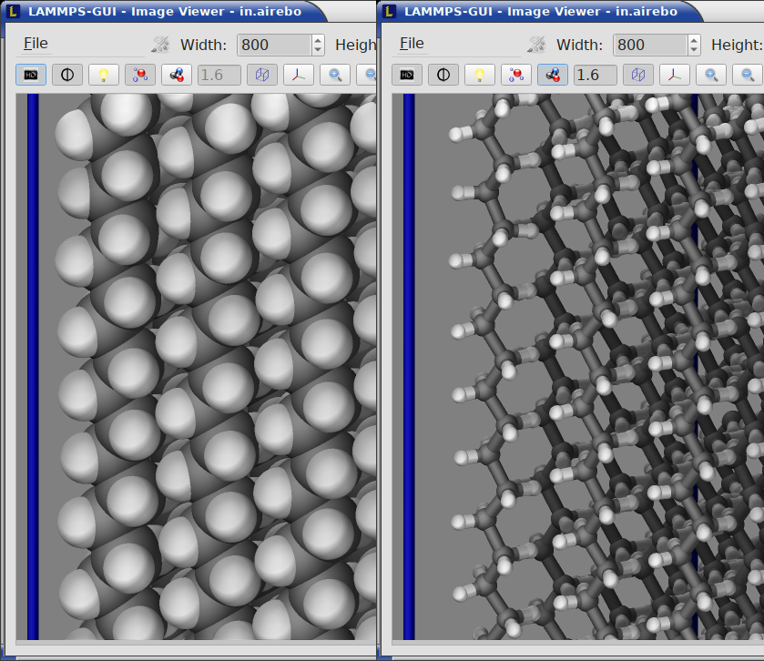
VDW style (toggle): Switch between space-filling (Van der Waals) sphere representation of atoms and the smaller ball-and-stick style of atoms and bonds.
Dynamic bonds (toggle): Automatically compute bonds from atom distances. This is useful for force fields with implicit bonds. When enabled, the adjacent text field allows setting the bond cutoff distance. This feature depends on existing neighbor list data and thus may not always work as expected when the system has explicit bonds and thus neighbors may be automatically excluded from neighbor lists due to the special_bonds settings
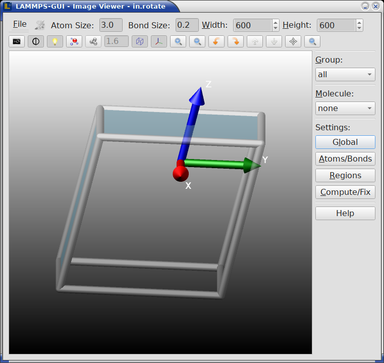
Box (toggle): Show or hide the simulation box drawn as colored cylinders.
Axes (toggle): Show or hide the labeled coordinate axes arrows.
Zoom in / Zoom out: Adjust the zoom level between in 10 percent increments between 0.1x and 10.0x.
Rotate left / Rotate right: Rotate the view horizontally by 10 degrees per click.
Rotate up / Rotate down: Rotate the view vertically by 10 degrees per click.
Recenter: Recenter the view on the center of mass of the currently selected group.
Reset: Reset the view to the default orientation and zoom level.
The default image size, some default image quality settings, the view style and some colors can be changed in the Preferences dialog window. From the image viewer window further adjustments can be made: actual image size, high-quality (SSAO) rendering, anti-aliasing, view style, display of box or axes, zoom factor. The view of the system can be rotated horizontally and vertically.
The settings panel on the right side of the window provides additional controls (most are explained in detail below):
Group: A drop-down list to select which group of atoms to display (default is “all”). Only atoms belonging to the selected group are rendered.
Molecule: A drop-down list to select a molecule to visualize (default is “none”). When a molecule is selected, it is shown at the center of the simulation box, and the group selection is disabled. Selecting “none” restores normal group-based display.
Global: Opens the Global image settings dialog for fine-grained control of axes, box, background, quality, and center settings.
Atoms/Bonds: Opens the Atom and bond settings dialog for detailed atom, bond, VDW, and special atom style visualization options.
Regions: Opens the Region settings dialog to configure visualization of regions defined in the simulation.
Compute/Fix: Opens the Compute and fix graphics dialog to enable and configure extra graphics objects provided by selected compute and fix styles.
Colors: Opens the Atom Type Color Customization dialog where the current list of colors used for per-type coloring can be customized and saved or loaded from a file.
Help: Opens this online documentation page for the visualization features in LAMMPS-GUI in a web browser.
The image is re-rendered after each change to the buttons, text fields or settings dialogs, and when there are many atoms to render and high quality images with anti-aliasing are requested, re-rendering may take several seconds. Some time consuming rendering steps are multi-threaded, but there is no GPU acceleration.
5.1.5. Global image settings
While some persistent default settings for the image output can be configured in the “Snapshot Image” tab of the Preferences dialog, more fine-grained configuration is possible by opening the “Global image settings” dialog. However, settings not stored by the preferences are reset when the image viewer window is closed. This dialog is opened by pressing the “Global” button in the settings panel or by using the Alt-L keyboard shortcut. The settings in this dialog correspond to options of the LAMMPS dump image and dump_modify commands.
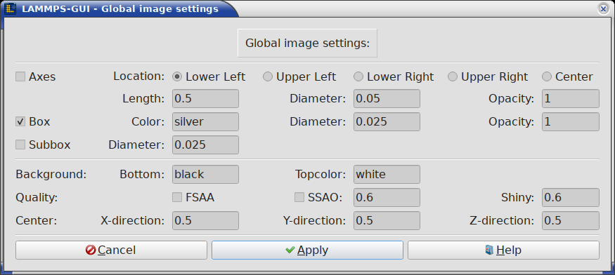
The dialog is organized into the following sections:
- Axes
Controls the display of coordinate axes arrows in the image.
Axes (checkbox): Enable or disable rendering of coordinate axes.
Location (radio buttons): Select where the axes are drawn in the image. Possible choices are: Lower Left (default), Lower Right, Upper Left, Upper Right, or Center.
Length: The length of the axes arrows as a fraction of the box size (range: 0.00001 – 5.0).
Diameter: The diameter of the axes arrows as a fraction of the box size (range: 0.00001 – 5.0).
Opacity: The transparency of the axes (range: 0.0 – 1.0, where 1.0 is fully opaque and 0.0 is fully transparent).
- Box
Controls the display of the simulation box.
Box (checkbox): Enable or disable rendering of the simulation box.
Color: The color used to draw the box edges. Accepts named colors.
Diameter: The diameter of the box edge sticks as fraction of the box size (range: 0.000001 – 5.0).
Opacity: The transparency of the box edges (range: 0.0 – 1.0, where 1.0 is fully opaque and 0.0 is fully transparent)
- Subbox
Controls the display of the per-processor sub-domain boxes (relevant for MPI parallel simulations, will coincide with the regular box for LAMMPS-GUI runs).
Subbox (checkbox): Enable or disable rendering of the sub-domain box.
Diameter: The diameter of the sub-domain box edge sticks as fraction of the box size (range: 0.00001 – 5.0).
- Background
Sets the background color(s) of the rendered image.
Bottomcolor: The background color at the bottom of the image.
Topcolor: The background color at the top of the image. If the two colors differ, a vertical gradient is applied from bottom to top.
- Quality
Controls rendering quality options.
FSAA (checkbox): Enable or disable full-scene anti-aliasing.
SSAO (checkbox): Enable or disable Screen Space Ambient Occlusion for depth-shaded rendering.
SSAO strength: The strength of the SSAO effect (range: 0.0 – 1.0).
Shiny: The shininess factor for surface rendering (range: 0.0 – 1.0, where 0.0 is matte and 1.0 is fully shiny).
- Center
Adjusts the center point of the rendered view.
X-direction, Y-direction, Z-direction: Fractional coordinates (range: 0.0 – 1.0) specifying the center of the view relative to the simulation box.
- Lighting
Adjusts the settings for the four light sources used in the rendering. Each value is a floating point number (range: 0.0 – 1.0) representing the intensity of the respective light source.
Ambient: The intensity of the uniform, non-directional base lighting that illuminates all parts of the scene equally.
Key: The intensity of the primary, directional light source that provides the main illumination and highlights.
Fill: The intensity of the secondary directional light source that fills in the shadows created by the key light.
Back: The intensity of the tertiary directional light source that illuminates the back of the objects, helping to separate them from the background.
Press Apply to apply the current settings and re-render the image, or Cancel to discard changes. The Help button opens the LAMMPS dump image documentation.
5.1.6. Atoms/bonds settings
This dialog offers more detailed customizations for atom and bond visualization that are not directly accessible from the main Image Viewer toolbar. It is opened by pressing the “Atoms/Bonds” button in the settings panel or by using the Alt-A keyboard shortcut.
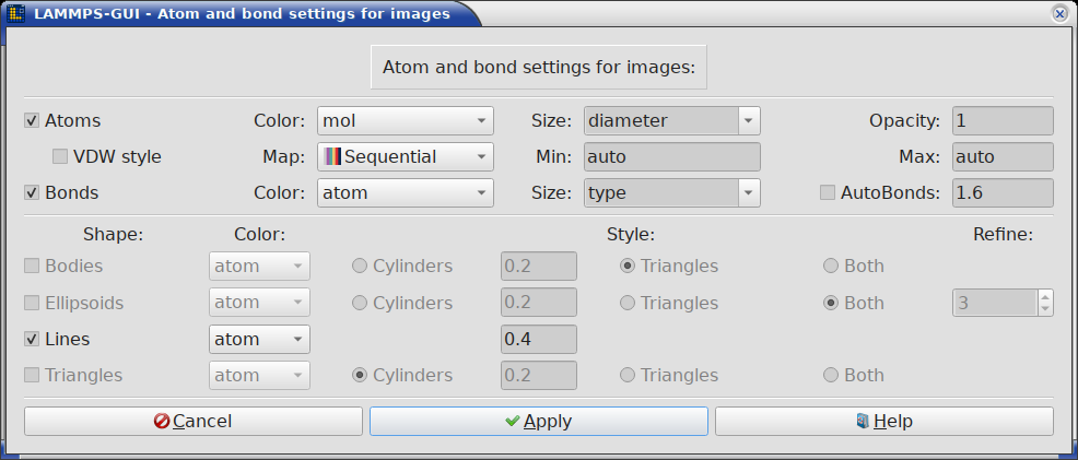
The dialog contains the following sections:
- Atoms
Controls how atoms are rendered.
Atoms (checkbox): Enable or disable rendering of atoms.
Color: Select the per-atom property used for coloring. Options include type, element (if detected), mol, q (charge), diameter, id, mass, x/y/z (coordinates), as well as atom-style variables (v_<name>), per-atom compute results (c_<name> or c_<name>[col]), and per-atom fix results (f_<name> or f_<name>[col]). The contents of the list depends on which are available in the current simulation state. When selecting type or element the colors are fixed and can be only changed manually for
dump_imageoutput in the input usingdump_modify acolorordump_modify element, respectively. Otherwise, the colors are determined by the colormap selection described below.Size: Select the property used for atom sizing. Options include auto (when element, diameter, or sigma data is available), type, element, and a few pre-defined choices for custom atom diameters. The text field can be edited and a different custom diameter entered.
Opacity: The transparency of atoms (range: 0.0 – 1.0, where 1.0 is fully opaque and 0.0 is fully transparent). Bonds have their own Opacity setting in the Bonds section below.
Map: Select the colormap used for coloring by a per-atom property. This option is not available for atom color selections type and element. Currently available continuous colormaps are: RWB (red-white-blue), PWT (purple-white-teal), BWG (blue-white-green), BGR (blue-green-red), Grayscale (black-white), Viridis (from matplotlib), Plasma (from matplotlib), Inferno (from matplotlib), Magma (from matplotlib), Cividis (from matplotlib), Turbo (from matplotlib), Teal, and Rainbow. Sequential, Landscape, and Basic are maps with discrete colors. These are pre-defined colormap settings and currently cannot be adjusted from LAMMPS-GUI directly. As for all image settings, further customizations can be realized by copying the dump image command line as customized by the Image Viewer to the editor and then run LAMMPS and observe the resulting images in the Slideshow Viewer window. Then the color map setting can be fully customized according to the dump_modify colormap documentation.
Reverse (checkbox): Mirror the selected colormap so its low and high ends are swapped (for example, RWB becomes blue-white-red). This replaces the former BWR entry, which is exactly RWB reversed. Enabled together with the Map selector.
Min / Max: Set the range of the colormap. Use auto to have LAMMPS determine the range automatically or specify an explicit numeric value.
VDW style (checkbox): Enable or disable space-filling sphere rendering. When unchecked, the ball-and-stick style is used. This toggle shares a line with the AutoBonds control of the Bonds section below; the two are mutually exclusive.
The color maps available for coloring atoms and bonds by value are shown below; the continuous maps are interpolated between color stops, while Sequential, Landscape, and Basic use discrete colors.
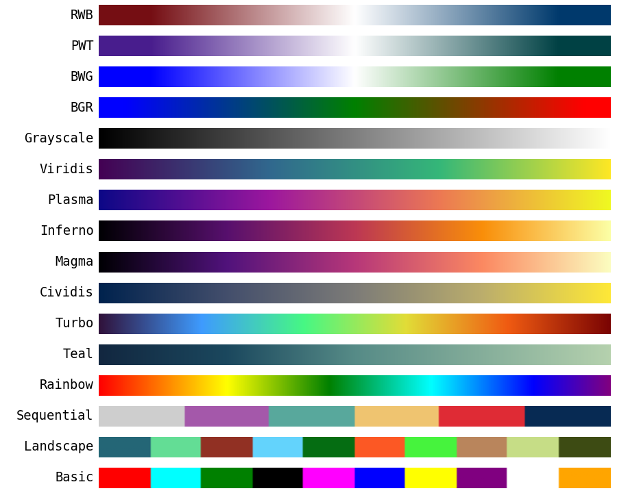
The dump-image color maps offered for coloring atoms and bonds by value.
These color maps are defined in a single table in the C++ source, which makes them simple to add or modify; see Adding or modifying a color map in the Programmer’s Guide for step-by-step instructions.
- Bonds
Controls bond visualization.
Bonds (checkbox): Enable or disable bond rendering. This option is only available when the atom style supports explicit bonds.
Color: Select the bond coloring mode. The basic choices are atom (each bond half is colored by the atom type at its end) and type (a uniform color per bond type). The list also offers a set of per-bond properties computed by
compute bond/local– dist, dx, dy, dz, engpot, force, fx, fy, fz, engvib, engrot, engtrans, omega, and velvib. Selecting one of these colors the bonds by that per-bond value using the bond colormap (see Map below); LAMMPS-GUI creates the requiredcompute bond/localautomatically.Size: Select bond diameter mode. Options include atom, type, and a few pre-defined choices for custom bond diameters. The text field can be edited and a different custom diameter entered.
Opacity: The transparency of bonds (range: 0.0 – 1.0), set independently from the atom opacity.
AutoBonds (checkbox): Automatically determine bonds from atom distances, useful for many-body force fields with implicit bonds like AIREBO or Tersoff. This feature depends on existing neighbor list data and thus may not always work as expected when the system has explicit bonds and thus neighbors may be automatically excluded from neighbor lists due to the special_bonds settings
Cutoff: The distance cutoff used for automatic bond detection (range: 0.001 – 10.0 in distance units), in the text field next to the AutoBonds checkbox. Only available when auto-bonds are enabled.
Reverse / Map / Min / Max: Select the colormap and value range used when coloring bonds by a per-bond value (see Color above). The same colormaps as the atom Map are offered, and the Reverse checkbox mirrors the chosen map exactly like its atom counterpart. These fields are only enabled when a per-bond property is selected as the bond color. Use auto for Min / Max to let LAMMPS determine the range automatically.
- Bodies
Controls visualization of body particles (when present in the simulation).
Bodies (checkbox): Enable or disable rendering of body particle shapes. When disabled, the particles are rendered as spheres like regular atoms.
Color (selection): Use coloring by the atom color choice, the body index, or the atom type of the body particles.
Style (radio buttons): Select the body rendering style – Cylinders, Triangles, or Both. For cylinders - when used for body particle rendering - also their diameter can be set (range: 0.1 – 10.0).
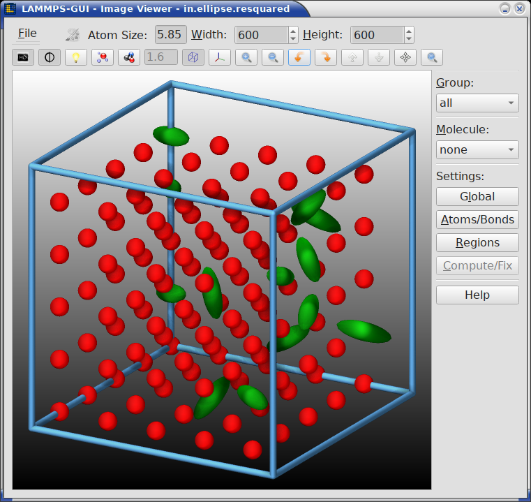
- Ellipsoids
Controls visualization of aspherical particles (when present in the simulation). Particles flagged as ellipsoids are represented as a triangle mesh, others as spheres.
Ellipsoids (checkbox): Enable or disable rendering of ellipsoid particle shapes. When disabled, the particles are rendered as spheres like regular atoms.
Color (selection): Use coloring by the atom color choice, the ellipsoid index, or the atom type of the ellipsoid particles.
Style (radio buttons): Select the ellipsoid rendering style – Cylinders, Triangles, or Both. For cylinders - when used for ellipsoid particle rendering - also their diameter can be set (range: 0.1 – 10.0).
Refine (spinbox): Level of triangle mesh refinement. At level 1 the ellipsoids are represented by a deformed octahedron. With a level increase, each triangle is replaced by 4 triangles following the ellipsoid shape more closely (max: 6). At the maximum level each ellipsoid is represented by 8192 triangles. At high refinement level, there may be artifacts from rounding due to limitations of the image rasterizer included in LAMMPS. These can be made less prominent by enabling anti-aliasing.
- Lines
Controls visualization of line segment particles (when present in the simulation).
Lines (checkbox): Enable or disable rendering of line segment particle shapes as connected cylinders. When disabled, the particles are rendered as spheres like regular atoms. Also the cylinder diameter can be set (range: 0.1 – 10.0).
Color (selection): Use coloring by the atom color choice, the line index, or the atom type of the line particles.
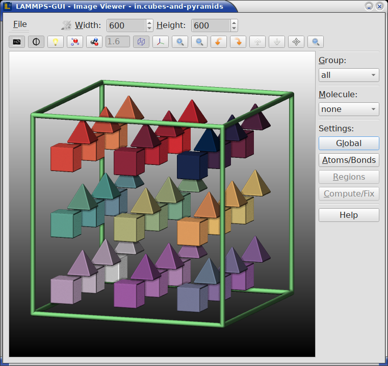
- Triangles
Controls visualization of triangulated particles (when present in the simulation).
Triangles (checkbox): Enable or disable rendering of triangulated particle shapes. When disabled, the particles are rendered as spheres like regular atoms.
Color (selection): Use coloring by the atom color choice, the triangulated particle index, or the atom type of the triangulated particles.
Style (radio buttons): Select the particle rendering style – Cylinders, Triangles, or Both. For cylinders - when used for triangle particle rendering - also their diameter can be set (range: 0.1 – 10.0).
Press Apply to apply the settings and re-render the image, or Cancel to discard changes. The Help button opens the LAMMPS dump image documentation.
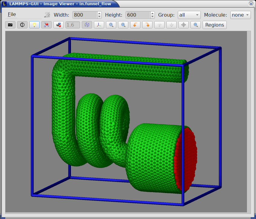
5.1.7. Region settings
This dialog allows enabling and configuring the visualization of regions defined in the LAMMPS input script. It is opened by pressing the “Regions” button in the settings panel or by using the Alt-R keyboard shortcut. The dialog only appears when at least one region is defined in the current simulation.
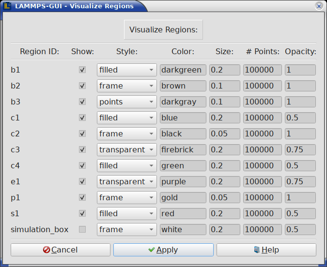
For each region, the following settings can be adjusted:
Region ID: The identifier of the region (read-only).
Show (checkbox): Enable or disable visualization of this region.
Style: The rendering style for the region surface – frame (wireframe), filled (solid), transparent (see-through solid), or points (point cloud).
Color: The color used to render the region. Accepts named colors or hex color values.
Size: The diameter of the lines (for frame style) or points (for points style).
# Points: The number of points used to approximate the region volume (range: 100 – 1,000,000). Higher values reproduce the volume better, but may obscure other details of the image.
Opacity: The transparency of the region rendering (range: 0.0 – 1.0, where 1.0 is fully opaque and 0.0 fully transparent).
Press Apply to apply the settings and re-render the image, or Cancel to discard changes. The Help button opens the LAMMPS visualization howto documentation and jumps to the section discussing visualizing regions.
5.1.8. Graphics from computes and fixes
Some compute and fix styles can prepare lists of graphics objects for inclusion into visualizations generated by the dump image command. This command is used internally by LAMMPS-GUI to create the snapshot image.
The “Visualize Compute and Fix Graphics Objects” dialog allows enabling these graphics objects and adjusting their settings. The dialog is opened by pressing the “Compute/Fix” button in the settings panel or by using the Alt-C keyboard shortcut. The dialog only appears when at least one compute or fix with graphics capabilities is defined.
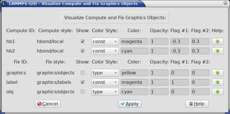
For each compute or fix that supports graphics output, the following settings can be adjusted:
Compute/Fix ID: The identifier of the compute or fix (read-only).
Style: The compute or fix style name (read-only).
Show (checkbox): Enable or disable visualization of the graphics objects from this compute or fix.
Color Style: Select the coloring mode – type, element, or const (constant color).
Color: The color to use when const color style is selected. Accepts named colors or hex color values.
Opacity: The opacity of the graphics objects (range: 0.0 – 1.0).
Flag #1 / Flag #2: Style-specific numeric flags that control additional rendering options. Their meaning depends on the specific compute or fix style.
Each row also has a Help button that opens the LAMMPS documentation page for the corresponding compute or fix style, jumping directly to the “Dump image info” section that describes the available graphics objects and flag settings.
Press Apply to apply the settings and re-render the image, or Cancel to discard changes. The general Help button at the bottom opens the LAMMPS dump image documentation.
5.1.9. Atom Type Color Customization
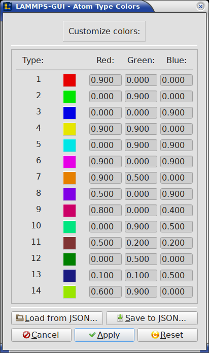
This dialog allows customizing the current color definitions used for per-type coloring, reset them to the default settings, and load or save them using JSON format files.
The dialog contains as many color rows as the current system has atom types and it is initialized from the current list of colors. If there are fewer types, then only the first part of that list is used. If there are more types, then the list of colors is used multiple times and wraps around. When the list is too long to fit into the dialog window, it can be scrolled up and down as needed.
The changes are applied to the image only after the “Apply” button is clicked and the dialog closed. At this step, the list of colors is updated with the colors in the dialog and expanded, if needed. When the “Cancel” button is pressed, the edits are discarded and the original list of colors retained. Clicking on the “Reset” button will reset the list of colors to its default values.
With the “Load from JSON” button a list of definitions for per-type colors is loaded from a JSON format file. The list may contain either more or fewer definitions than the current system has atom types. The “Save to JSON” button instead saves the edited list of definitions to a file. The list may be loaded later to restore a previous color assignment.
JSON file format for colors and lighting definitions
The JSON format file for color and lighting definitions has the following structure and is compatible with the format used by the LAMMPS commands dump_modify savecolors and dump_modify loadcolors. The file can be validated with the JSON schema file at https://download.lammps.org/json/color-schema.json.
The “application”, “format”, “revision” entries are required and are checked for on reading so that files without them are rejected. Also the “colors” list is required with color definitions of three entries each: “red”, “green”, and “blue” that have the value of the corresponding color component given as a floating point number in the range from 0.0 to 1.0 inclusive. The “lights” object is optional (LAMMPS-GUI will display a warning if it is missing) and contains the intensity settings for the four light sources: “ambient”, “key”, “fill”, and “back” also in the range from 0.0 to 1.0 inclusive.
Here is an example with just two colors (red and green) and default lighting settings:
{
    "application": "LAMMPS",
    "format": "colors",
    "revision": 1,
    "schema": "https://download.lammps.org/json/color-schema.json",
    "colors": [
       {
           "blue": 0,
           "green": 0,
           "red": 0.9
       },
       {
           "blue": 0,
           "green": 0.9,
           "red": 0
       }
    ],
    "lights": {
       "ambient": 0.2,
       "back": 0.4,
       "fill": 0.4,
       "key": 0.4
    }
}
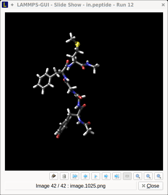
5.2. Image Slide Show
When running a LAMMPS input containing a dump image command with LAMMPS-GUI, the “Slide Show” window opens to load and display the images created by LAMMPS as they are written. This is a convenient way to visually monitor the progress of the simulation. It also can be used as an effective way to refine visualizations created with the Snapshot Image Viewer.
The same window can also display existing image files that were not created by the current session: select one or more files with File -> Open Image File(s) (see the File menu) to review images produced by an external (for example large parallel) simulation, or to revisit images from an earlier run without rerunning it. Image formats that Qt cannot read natively are converted on demand with ImageMagick if it is available. When the slide show is opened this way, the controls that act on a running simulation (such as stopping the run or sending images to the trash) are hidden.
Added in version 2.1: Existing image files can be loaded into the slide show with Open Image File(s), and image files opened with File -> View are shown here instead of as text.
From the slide show window the following global keyboard shortcuts are supported: Ctrl-W: close window, Ctrl-Q: quit application, Ctrl-/: stop running simulation. Other keyboard shortcuts are connected to some of the controls and listed in their documentation below.
5.2.1. Slide show controls
There are controls and displays above and below the image. If you are uncertain about the function of a specific button, you can place the cursor on top of it and a descriptive tooltip will appear.
The toolbar at the top of the Slide Show window provides the following controls, organized from left to right:
Export to movie (Ctrl-E): Export the active range of images (see the Start and Stop controls below) to a movie file or animated GIF file. This requires that either the FFmpeg program or the ImageMagick software are installed. Supported output formats include MP4, MKV, AVI, MPG, MPEG, WEBM, and animated GIF. The file format is determined by the file name extension. Any active image transformations (rotation, mirroring, see below) are applied to the exported movie.
Save current image (Ctrl-S): Save the currently displayed image to a file, including any applied transformations (rotation, mirroring, see below). The file format is inferred from the file name extension. When the ImageMagick software is installed, additional file formats beyond those natively supported by the Qt library become available.
Copy to clipboard (Ctrl-C): Copy the current image to the system clipboard for pasting it into another application. This requires support from the receiving application, which is the case for many common applications like document editors and web browsers.
Delete selected images: Remove the image files in the currently selected range (see the Start and Stop controls below) from disk. A confirmation dialog reports how many files will be removed before they are deleted. With the default range (first to last image) this removes the entire sequence. Since the number of image files can be large for long simulations, this provides a safe way to clean up the working directory without risk of accidentally deleting other files. This will, however, only delete images of the last run. If that was stopped before completion or the output filename has changed, older images created by previous runs will not be deleted.
Zoom in: Increase the displayed image size by scaling it up. Every click on the button increases the zoom factor by 10 percent.
Zoom out: Decrease the displayed image size by scaling it down. Every click on the button decreases the zoom factor by 10 percent until a minimum zoom factor of 0.1.
Rotate clockwise: Rotate the displayed image 90 degrees clockwise.
Rotate counter-clockwise: Rotate the displayed image 90 degrees counter-clockwise.
Mirror horizontally: Flip the displayed image along the vertical axis.
Mirror vertically: Flip the displayed image along the horizontal axis.
Reset image: Reset the displayed image to the original image. This reverts all zoom, rotate, and mirror operations.
Stop Simulation (Ctrl-/): Stop a running simulation.
These image transformations are useful when the simulation images need to be adjusted for presentation purposes. The same transformations are also applied when exporting images or movies.
The playback controls below the image allow to select the displayed image, restrict the active range, and control the slideshow settings:
Play: Start playing the animation, advancing through the active range defined by the Start and Stop controls.
Loop: Toggle continuous looping of the animation. When enabled, playback wraps around from the last image of the active range back to the first.
Delay: Set the delay in milliseconds between frames during animation playback.
Start: First image of the active range. Animation, single stepping, movie export, and image deletion are all restricted to images at or after this position. Defaults to the first image.
Stop: Last image of the active range. Defaults to the last image and keeps following the growing sequence while a simulation produces new images, unless it has been set to a specific value.
First: Jump to the first image of the active range.
Previous: Step back to the previous image.
The slider control selects a frame in the image sequence by moving the slider position. Its track is colored to indicate the active range: positions inside the Start to Stop range are drawn in blue, while the skipped images outside it are drawn in red.
Next: Step forward to the next image.
Last: Jump to the last image of the active range.
Added in version 2.1: The Start and Stop controls restrict animation, single stepping, movie export, and deletion to a selected range of images, and the navigation slider highlights that range in color.